|
|
|
|
|
|
|
Controlling NOx On Refinery Heaters |
|
|
Using CO Based Control Technology
CO based combustion controls for refinery heaters provide a number of benefits. With the focus on reducing excess air and the resultant fuel savings, many refinery engineers are not aware of the additional environmental benefits that result from CO based control technology.
As an example, four refinery process heaters – (3) natural draft and (1) forced draft have been recently retrofitted with CO based combustion control systems.
This project provides the ideal opportunity to examine and quantify the environmental benefits made available by this technology on different types of heaters. This paper will:
- Review the heaters’ characteristics,
- Discuss operation of the heaters prior to installation of CO based controls,
- Explain the technology implemented, and
- Detail the resultant performance benefits.
In addition to the emissions reductions, improvement is seen in heater efficiency with associated fuel gas savings as expected.
Introduction
The refinery wanted to become more fuel efficient in their process heaters and reduce NOx to the extent possible. There was an opportunity to achieve both of these with the same technology. It is common knowledge that CO based combustion control of process heaters can reduce operating costs by minimizing fuel requirements, but the reduction of NOx associated with this control method is not commonly understood.
Background
Process heaters and boilers are typically operated with excess combustion air to ensure that an adequate amount of oxygen is available for combustion, particularly during transient conditions. Operating with insufficient air hurts energy efficiency, increases CO emissions, and in extreme cases can produce conditions that might lead to a heater explosion. Operating with too much air hurts energy efficiency and increases NOx emissions.
Flue Gas Analyzers
To guard against a condition of insufficient combustion air, flue gas combustion analyzers were typically installed to measure the absence of excess air.
When used in a safety shutdown system, the design must guard against false trips and nuisance alarms.
The previously best available analyzer technology takes a sample at a point near the top of the furnace for the measurement. This accurately measures only at that one point in the furnace, and can only serve as an approximation of the condition in the remainder of the furnace.
Flue gas moves directly from each of the burners to the exit of the furnace. This takes place in 2 to 4 seconds and allows no time for the flue gas between burners to mix. Thus, point sample analyzers measure accurately only the burner directly up-stream from the sample point.
The classic analyzers, used for combustion safety or control, are not installed above the convection section or in the stack because of the potential for air leakage and resultant errors in the readings. These analyzers can thus provide a false sense of security.
Continuous Emissions Monitoring Systems (CEMS) are not useful for combustion control for two reasons:
- Installation in the stack makes them subject to air leakage.
- Time delay for measurement – They extract the sample, and move it to grade for the analysis.
Combustion Upsets
The following issues make low excess air control more difficult in refineries:
- Refinery fuel gas is typically a mixture of residual gases generated by the various processing units and natural gas (as purchased make-up fuel). Variations in the Btu content can be expected throughout the day, when changing operating modes, and as catalytic units change yields from start-of-run to end-of-run.
- Process upsets can and do happen. Gases that are not normally burned as fuel can be dumped into the fuel system, immediately and significantly changing the Btu content.
- Changes in heater duty requirements can occur frequently, resulting in many adjustments in the fuel rate to achieve the necessary Btu release.
Conclusions Driving CO Based Combustion Control
Without advanced controls, refinery heaters are often operated with 3 to 4 percent O2 in the flue gas. This gives a margin of safety for operators to be able to react to the uncertainty of flue gas measurement, random changes in the firing rate, and changes in the Btu content of the fuel. Heaters can be fired near stoichiometric combustion ratios to give significant fuel savings and NOx reductions – but only if the following elements are included in a control package:
- An analyzer that measures most or all of the furnace flue gas,
- An analysis method that is fast enough to measure CO levels well before an explosive condition can be created,
- A control action that is fast enough to react to the dynamics of combustion, and
- An adequately trained staff of operators and engineers.
Reducing air to produce trace CO content in the flue gas, and controlling using flue gas CO as the control variable is a natural solution.
|
|
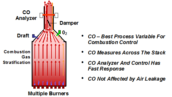
CO Is The Best Control Parameter For The Following Reasons
CO – Best Process Variable for Combustion Control
The primary reason for watching O2 levels in a heater is to prevent a condition where insufficient air is being provided to completely combust all the fuel being introduced into a furnace. Incomplete combustion can produce significant amounts of CO and lead to an explosive condition if not corrected immediately
Without CO based control, the safest way to operate is with a safety factor of excess oxygen, typically in the range of 2 to 4 percent O2 in the flue gas. But this is actually 12 to 26 percent excess air (above the stoichiometric combustion requirements). This excess air "cushion" is required for safety due to the following facts:
- In furnaces with standard O2 analyzer probe locations and multiple burners, there is no safe way to ensure that each burner has sufficient air to complete combustion. Gas flow paths from burners that are not "in line" with the O2 analyzer probe may not get represented in the analysis.
- Leaks in the O2 analyzer calibration line can cause false high readings leading to insufficient air for combustion.
- Air leaking into the furnace below the O2 analyzer can also cause false high readings, leading to insufficient air for combustion.
- O2 analyzers are relatively slow to react; forcing the control strategy tuning to be slow compared to CO based control. A cushion of excess air is often used to allow for the slower control reaction time.
With CO control, the heater combustion is controlled between 50 and 100 ppm CO with 200 to 500 ppm excursions. This never allows excess combustibles to cause a furnace incident, as these concentrations are well below the combustibles LEL of 20,000 to 40,000 ppm
Beginning with complete combustion, as excess air is minimized, CO acts as the precursor of combustion concerns.
Concerns the refinery improved by choosing CO based control:
- Burner flameout. Before this happens, the burner will emit CO. The control needs to add enough air to stabilize the burner. Very high levels of CO are produced before flame instability or flame lift off is reached. CO based control ensures these levels will not be reached.
- Ultra low NOx burners have burner tip plugging issues. When a burner tip begins to plug, it will emit CO. The control scheme will open dampers appropriately, adding enough air to keep CO on the set-point. This will produce higher O2 on CO control than normal and operators will thus be notified of a combustion condition needing attention.
- Burner registers can be set improperly or differently than the other registers. CO control highlights this condition, and when corrected will ensure maximize efficiency while maintaining safe excess air.
- Flame impingement. This situation will create CO. When a flame touches a cooler surface, like a tube or a wall, the flame will extinguish. Any fuel still left after the flame was extinguished will show up as CO.
- Large BTU fluctuations and plant upsets. These situations will be noticed within seconds and compensated for quickly. Excursions do occur for a few seconds.
- Afterburning. CO is detected in small quantities before the concentrations become large enough to support significant "after-burn."
CO Measurement Across the Stack
The CO analyzer measures the flue gas by utilizing a light beam across the stack. Because the measurement position is located after the convection section, this allows for measurement of the total stream of combustion products leaving the heater.
CO Analyzer And Control Have Fast Response
The CO analyzer has a response time of 0.15 second, and provides controller input once per second. This facilitates efficient operation, since lower excess air operation requires faster control action than other analyzers can support.
CO Is Not Affected by Air Leakage
The light beam CO analyzer is installed after the convection section, and measures only the products of combustion. Since CO is not present in significant quantities in ambient air, the analyzer is not affected by leakage.
Case Studies - Heater Characteristics
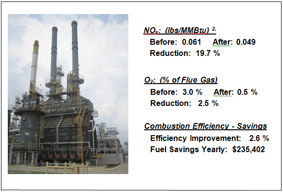
Crude Heater
- Type of Heater: Natural draft, box type, common convection section, 2 stacks
- Hardware Supplied: 2 CO Analyzers, 2 Damper actuators
- Firing Rate: 150 MMBtu/Hr
- Duty: Between 800px and 75% of full firing rate
- Burners: Qty. (12) - side fired
- CO Set-point: 50 ppm with occasional excursions to 350 ppm
- Fuel Savings: Based on purchased fuel of $7.00 per MMBtu 1.
|
|
|
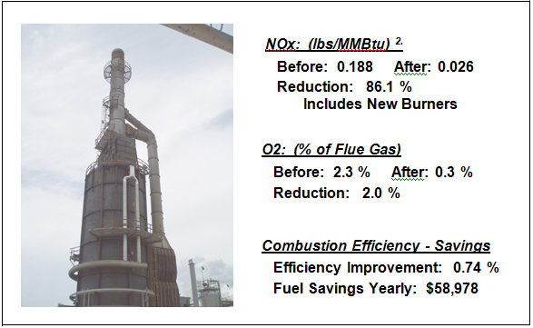
Hot Oil Heater
- Type of Heater: Forced draft, vertical can, single convection section, 1 stack
- Hardware Supplied: CO Analyzer
- Firing Rate: 130 MMBtu/Hr
- Duty: Between 800px and 75% of full firing rate
- Burners: Qty. (8) bottom fired, new low NOx burners
- NOx Reduction: Includes reduction from installing new burners
- CO Set-point: 25 ppm with excursions to 250 ppm
- Fuel Savings: Based on purchased fuel of $7.00 per MMBtu 1.
|
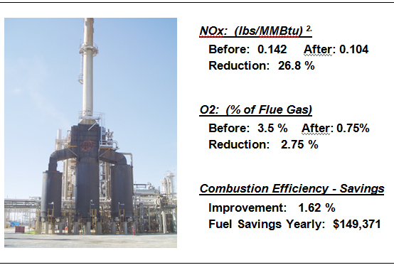
Reformer
- Type of Heater: Natural draft, 3 can, single convection section, 1 stack
- Hardware Supplied: CO Analyzer, Damper actuator, 3 Draft Transmitters
- Firing Rate: 150 MMBtu/Hr
- Duty: Between 800px and 75% of full firing rate
- Burners: Qty. (10) bottom fired
- CO Set-point: 50 ppm with excursions to 250 ppm
- Fuel Savings: Based on purchased fuel of $7.00 per MMBtu 1.
|
Vacuum Heater
- Type of Heater: Natural draft, vertical box, single convection section, 2 stacks
- Hardware Supplied: 2 CO Analyzers, 2 Damper actuators, 2 Draft Transmitters
- Firing Rate: 94 MMBtu/Hr
- Duty: Between 800px and 75% of full firing rate
- Burners: Qty. (12) bottom fired
- CO Set-point: 100 ppm with excursions to 500 ppm
- Fuel Savings: Based on purchased fuel of $7.00 per MMBtu 1.
1. The historical average NYMEX Henry-Hub Natural Gas price, rounded to the nearest dollar, for February through May 2006.
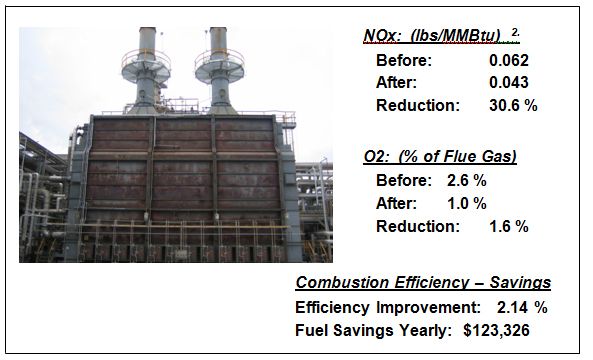
2. NOX "Before" data is from last stack test of record prior to installation of the CO based control system. "After" data is from the first stack test after installation.
The Technology Implemented
The technology in summary consists of three components.
Hardware, consisting of:
- CO Analyzer – A fast, high signal to noise ratio, 0 to 1000 ppm, light beam analyzer.
- Damper Actuator – An industrial standard, fast pneumatic actuator.
- Draft Transmitter – Plant standard, high sensitivity, differential pressure transmitter.
Control Strategy – Implemented in the unit DCS
The Control Strategy is designed to react fast throughout the control range and covers the concerns normally inherent in controlling with flue gas CO. This control strategy concept is a shift to CO as the feedback parameter.
Combustion Engineering, consisting of:
Heater Tuning - Operations Training
- Extensive training includes operations, maintenance, engineering and management, not only in the equipment and control strategy but also in the theory of CO based control.
- Key in the training is instructions for the operators to switch from CO based control back to manual control and increase the excess air if there are any concerns, since CO is not a mission critical control.
- CO control is not intended to fix combustion problems. It simply adjusts the air to keep the unit safe at all times. CO control will maximize the efficiency only if it is safe.
- Operations can also use the CO vs. O2 readings as a new tool to diagnose problems occurring in the furnace.
- If burner tips become fouled the O2 will climb while on CO control. This may be inefficient but the heater will stay safe.
Fundamental Theory of NOx Reduction With CO Based Control
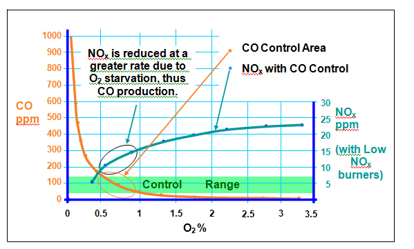
When the furnace is evenly producing CO in the trace amount and controlling on the CO set-point, there is a slight lack of Oxygen uniformly throughout the combustion zone.
This makes it extremely difficult for Nitrogen to find available Oxygen with which to combine to form Nitric Oxide within the time available. This must occur, before the combustion gases exit the combustion zone, where temperatures cool and will not allow the formation.
This situation becomes quite severe for the Nitrogen as the available excess air is reduced to the point of CO production. The higher the CO set-point allowed, the larger is the reduction of Oxides of Nitrogen formation.
The resultant NO exits the stack, combines with ambient Oxygen, and forms NO2 along with a few minor oxides of Nitrogen together commonly known as NOx.
Summary
NOx Reduction averaging 25 %
Ranging per heater from 20 to 30 %
Fuel Savings of $567,076 a year
Ranging per heater from $58,978 to $235,402
|
|
|
|
|